Contact tracing via smartphone apps has been widely touted as an important way to control and limit the spread of the COVID-19 epidemic. However, basing contact-tracing on phone apps has several limitations. Here are instructions for constructing a contact tracing device prototype with a Raspberry Pi Zero-W. The constructed device is compatible with the Apple/Google Bluetooth contact tracing specification. It runs the Epidose software, which is based on the DP3T “unlinkable” design.
Materials
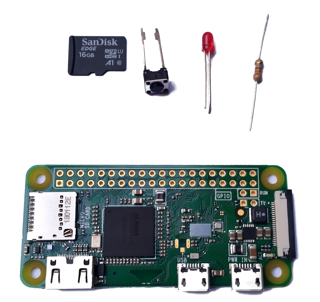
Assemble the following materials:
- Raspberry Pi Zero-W
- MicroSD card (minimum recommended size 8 GB)
- Small (3mm) red LED
- 330 Ohm, 0.25 W resistor
- Single SPST momentary push button upload of their contacts to the Health Authority.
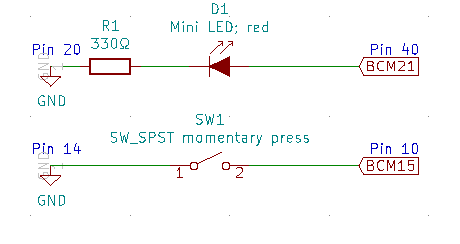
The objective of this construction is to provide the Raspberry Pi with a switch to authorize the contact upload and a LED to indicate that a user is at risk. The circuit diagram above shows this setup.
Connect the resistor to the LED
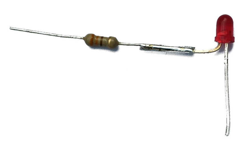
Solder one end of the resistor (it doesn’t matter which) to the LED’s cathode (the shorter of the LED’s two wires) to obtain a 17mm long connection. The connected assembly should be able to fit in pins 20 and 40 of the Raspberry Pi.
Isolate the LED-resistor connection
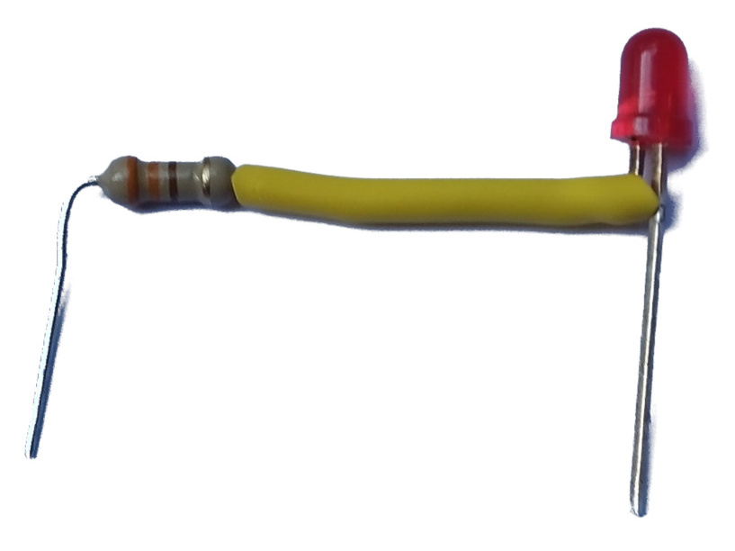
Cut a 17mm length from the smallest heat-shrink tube that can fit around the resistor, and slide it to cover the entire LED-resistor connection. Heat it to shrink.
Solder components on the Raspberry Pi
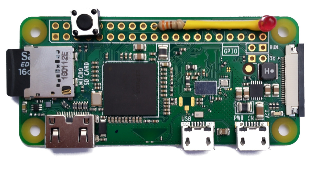
- Solder the free end of the LED (its anode) to pin 40.
- Solder the free end of the resistor to pin 20.
- Solder the push button between pins 14 and 10 (orientation isn’t important).
Power up and install the Epidose software
- Connect the Raspberry Pi to a power source. A USB power bank can make this setup portable.
- Follow the instructions in the Epidose repository repository to install and configure the software.
- You can test the hardware’s operation by running the command
sudo venv/bin/python epidose/device/device_io.py --test. This allows you to toggle the LED by pressing the button. Press Control-C and then press the button to terminate the program.


Why I Choose Email Over Messaging (2025-09-26)
Is it legal to use copyrighted works to train LLMs? (2025-06-26)
I'm removing the BSD advertising clause (2025-05-20)
The perils of GenAI student submissions (2025-04-11)
Unix make vs Apache Airflow (2024-10-15)
How (and how not) to present related work (2024-08-05)
An exception handling revelation (2024-02-05)
Extending the life of TomTom wearables (2023-09-01)
How AGI can conquer the world and what to do about it (2023-04-13)
Last modified: Wednesday, May 20, 2020 9:50 pm

Unless otherwise expressly stated, all original material on this page created by Diomidis Spinellis is licensed under a Creative Commons Attribution-NonCommercial 4.0 International License.